Go Board – Introducing Look-Up Tables (LUTs)
How Boolean Algebra is Actually Performed on an FPGA
Have you ever wondered how an AND gate actually works inside your FPGA? An AND gate is a type of logic circuit that has two inputs and one output. The output is equal to 1 only when both inputs are equal to 1. Unless both inputs are 1, the output will be 0. It’s a very simple Boolean logic circuit. Boolean logic simply means all variables can have the value 1 or 0 (or as sometimes called in FPGAs, high and low). There are other types of simple Boolean logic components: OR, NOT, XOR, NAND, etc. But have you ever considered how these are actually implemented inside of an FPGA? Are there really thousands of individual AND gates, just waiting to be wired up? That would not be very versatile. Instead, FPGAs use Look-Up Tables or LUTs. LUTs are a fundamental component used to perform all Boolean logic inside your FPGA. I also created a YouTube video for this project, should you prefer to follow along with that.
A truth table shows every possible input combination and what the resulting output will be. Let’s look at the truth table for an AND gate. Remember, the AND gate Output is 1 when input A AND input B are 1.
| Truth Table – A AND B | ||
|---|---|---|
| Input A | Input B | Output Q |
| 0 | 0 | 0 |
| 0 | 1 | 0 |
| 1 | 0 | 0 |
| 1 | 1 | 1 |
Now what if we wanted to change this to an OR gate? An OR gate means that the output will be 1 if input A OR input B are 1. If neither A OR B are 1, then the output will be 0. Let’s take a look at that truth table:
| Truth Table – A OR B | ||
|---|---|---|
| Input A | Input B | Output Q |
| 0 | 0 | 0 |
| 0 | 1 | 1 |
| 1 | 0 | 1 |
| 1 | 1 | 1 |
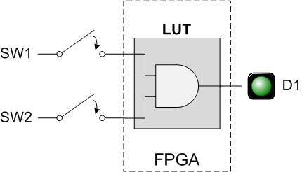
A Look-Up Table (LUT) is how any arbitrary Boolean logic gets implemented inside your FPGA. The above examples show a 2-input LUT that has been configured to be an AND gate and an OR gate. But given 2-inputs, there’s lots of possible output combinations, which all must be possible to satisfy given a 2-input LUT. Therefore, A 2-input LUT can implement any Boolean output given 2-inputs. There are 3-input, 4-input, and even 5-input LUTs on FPGAs. The Go Board uses LUT4s, which are 4-input LUTs. This means that any possible Boolean logic you can come up with given 1-output and 4-inputs can be programmed into a single LUT element. Note that you don’t actually need to have 4-inputs, you can use a single LUT to make a 2-input AND gate. The tools will simply tie off input 3 and input 4 if they are unused. Check this page for more detail about LUTs and Boolean Logic in general.
In a real FPGA, the output of one LUT can be routed (wired) into the input of another LUT. This allows you to create Boolean logic with five or more inputs, even if you only have LUT4s on your FPGA. It is the job of the synthesis tool to take your VHDL or Verilog code, extract any Boolean logic, and convert the Boolean equations into LUTs. A good synthesis tool will keep the utilization of these LUTs as low as possible. On the Go Board, there are a total of 1280 LUTs available for you to use. The previous project didn’t use a single LUT, but this one will.
Project Description
This project should illuminate LED D1 when both Switch 1 and Switch 2 are pushed at the same time
We are creating an AND gate! This is a very simple usage of a Look-Up Table. Only 2 inputs will actually be needed from the 4-input LUT. The tools will take care of all of this for you. On this page you’ll find both the Verilog and the VHDL code for this design. Let’s look at the Verilog code for this design.
Verilog Code – And_Gate_Project.v:
module And_Gate_Project
  (input i_Switch_1,
   input i_Switch_2,
   output o_LED_1);

assign o_LED_1 = i_Switch_1 & i_Switch_2;

endmodule
In the Verilog code above, we have introduced our first operator, the ampersand (&). This is known as a bitwise operator. In the code above, o_LED_1 will be 1 only when i_Switch_1 and i_Switch_2 are both 1. This means that you will need to push both of those buttons down to get the LED to illuminate.
VHDL Code – And_Gate_Project.vhd:
library ieee;
use ieee.std_logic_1164.all;

entity And_Gate_Project is
  port (
    -- Push-Button Switches:
    i_Switch_1 : in std_logic;
    i_Switch_2 : in std_logic;

    -- LED:
    o_LED_1 : out std_logic
    );
end entity And_Gate_Project;

architecture RTL of And_Gate_Project is
begin
  o_LED_1 <= i_Switch_1 and i_Switch_2;
end RTL;
In the VHDL code above, we have introduced our first operator, the keyword and. This is known as a logical operator. In the code above, o_LED_1 will be 1 only when i_Switch_1 and i_Switch_2 are both 1. This means that you will need to push both of those buttons down to get the LED to illuminate.
Your code is complete. Now you need to build the bitstream and program your FPGA. This follows the exact same process as the first project. Once the FPGA build process is complete, I would like to direct your attention to the Synthesis Report file. This can be viewed from within iCEcube2 by expanding Reports under Synthesis Tool. Double click the file and scroll to the bottom. You’ll see a report that shows the resource utilization on your FPGA. In our previous project, we were just using I/O ports (Input/Output), but now there’s a new element shown. We see that exactly one Look-Up Table (LUT) is being used! How exciting! You have successfully created an And Gate on an FPGA!
Resource Usage Report for And_Gate_Project

Mapping to part: ice40hx1kvq100
Cell usage:
SB_LUT4         1 use

I/O ports: 3
I/O primitives: 3
SB_IO          3 uses

I/O Register bits:                  0
Register bits not including I/Os:   0 (0%)
Total load per clock:

Mapping Summary:
Total  LUTs: 1 (0%)
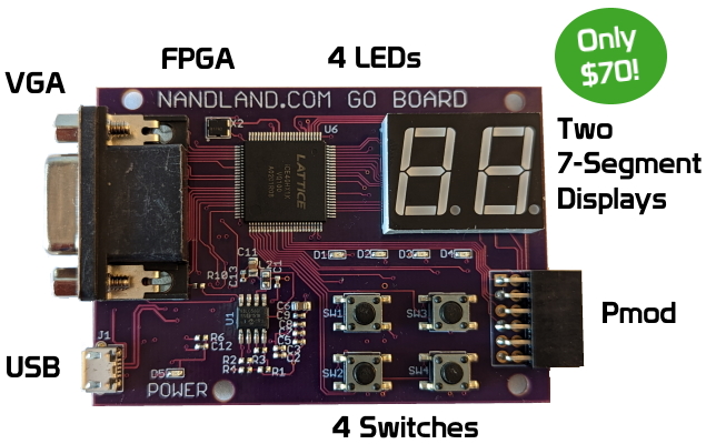
After programming your board, hold both SW1 and SW2 and the LED D1 should illuminate! You’ll notice that D2, D3, and D4 are always on, that’s OK. Congratulations, you now know what a LUT is! LUTs are used everywhere in your FPGA. They are used to make counters, state machines, if statements, lots! As you write more code the concept will get more comfortable. But LUTs are really only half of the story when designing FPGAs. As important as LUTs are, there’s another critical component on your FPGA: The Flip-Flop (AKA Register). Without Flip-Flops, FPGAs would be basically useless. So let’s learn about what a Flip-Flop is and how it plays such an important role in FPGA design.


I had done Project 1 prior to doing this And_Gate project. LED_1 only lit when both Switch 1 and Switch 2 were pressed at the same time. So, the program did behave correctly in that sense. However, my LED_3 and LED_4 lit up as soon as I loaded the program and they stayed lit no matter what switch I pressed. I ‘m guess that this might have been the result of having Project 1 previously on my Go Board. To get the performance that you show in your video, that is, with no LEDs lighting up ever except LED_1 and only per the AND instructions, I modified the Verilog code as follows:
module And_Gate
(input i_Switch_1,
input i_Switch_2,
output o_LED_1,
output o_LED_2,
output o_LED_3,
output o_LED_4
);
assign o_LED_1 = i_Switch_1 & i_Switch_2;
assign o_LED_2 = 0; // This sets LED_2 to off
assign o_LED_3 = 0; // This sets LED_3 to off
assign o_LED_4 = 0; // This sets LED_4 to off
endmodule
The LEDs are dimly lit due to an internal pull-up resistor. You can disable it if you want in iCEcube2, or override it by setting the output to 0 as you did.