Go Board – UART (Universal Asynchronous Receiver/Transmitter)
Learn to Communicate with the Computer (Part 1 – Receiver)
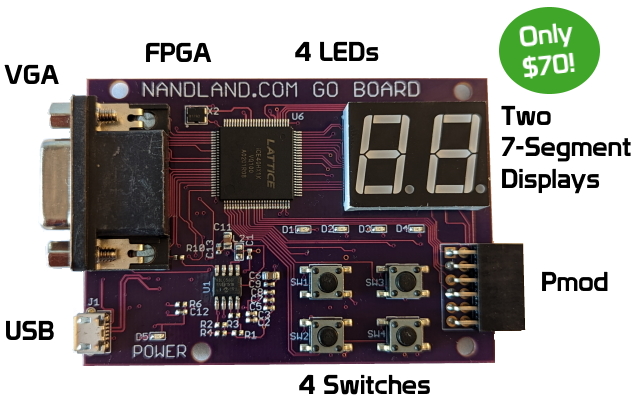
The Go Board has the Micro USB connector, which until this point we have only been using to power and program the FPGA. But there’s actual a third use for the USB connector: Communicating with the Go Board. This is made possible via the FTDI chip. The FTDI chip allows the Go Board to be viewed as a COM Port to your computer. This enables serial communication via a terminal emulator. My favorite terminal emulator program is Tera Term. I recommend downloading that program for use with this project.
If you prefer to follow along with a YouTube video I made, you can find that below:
What is a UART?
A UART is sometimes referred to as a Serial Port, RS-232 Interface, or COM Port. It’s one of the simplest methods of communication with your FPGA. Other methods of communication you might have heard of are PCI, PCI-Express, USB, etc, but the Go Board uses a UART because it’s the easiest and best to learn with.
The UART consists of a receiver component and a transmitter component. For the UART Receiver portion, we need to take in the serial data from the computer. This is sent by the computer one bit at a time. The receiver converts it back to the original byte. This is a conversion of serial data to parallel data.
The transmitter works in the opposite way. It sends out one byte at a time across a single wire. A byte is 8-bits wide, so in order to send a byte over a single wire, you need to convert the data from parallel data (as stored in the byte) to serial. This is what we will be doing in the UART Transmitter (Part 2 of this Project). I decided to break up the UART into two parts because it’s the most complicated project thus far.
UART Configuration Parameters
A UART has several parameters that can be set. The transmitter and the receiver need to agree on the settings below or data corruption occurs. Let’s discuss the UART parameters that are settable:
    Baud Rate            (9600, 19200, 115200, others)
    Number of Data Bits  (7, 8)
    Parity Bit           (On, Off)
    Stop Bits            (0, 1, 2)
    Flow Control         (None, On, Hardware)
Baud Rate is the rate at which the serial data is transmitted. 9600 Baud means 9600 bits per second. Number of Data Bits is almost always set to eight. A Parity Bit can be appended after the data is sent, to know if the data was received correctly or not. A Stop Bit always set to 1, and there can be 0, 1, or 2 Stop Bits. Flow Control is not typically used in present day applications and will likely be set to None.
State Machines
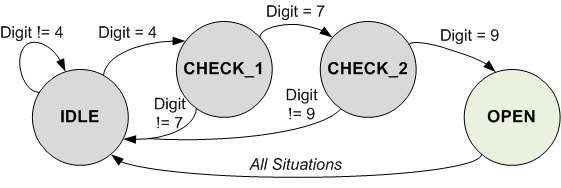
This is going to be the first project that uses a State Machine. You can write state machines to keep track of a sequence of steps inside of your FPGA. For example, if you have a 3-digit passcode to open a safe. Let’s assume the correct passcode is 479. This is a perfect opportunity to use a state machine. Refer to the figure below:
The states are represented by the circles. The transitions between states are represented by the arrows. The possible ways to transition between states are shown above the arrows. The code starts in an IDLE state. If the digit 4 is pressed, then we transition to CHECK_1. If any other digit is pressed, then the state machine stays in IDLE. Once we are in CHECK_1, we again wait for a button press, if we see the correct digit (7) we transition to CHECK_2, otherwise we go back to the IDLE state. Once we are in CHECK_2, then we are looking for the last digit of the passcode. If the last digit is a 9, then we go to OPEN state, which unlocks the safe, otherwise we go back to IDLE.
The UART code will be using a state machine in a similar way. The UART needs to keep track of the bits received or transmitted, and the easiest way to keep track of these bits is by using a state machine.
Project Description
Create a UART Receiver that receives a byte from the computer and displays it on the 7-Segment Displays. The UART receiver should operate at 115200 baud, 8 data bits, no parity, 1 stop bit, no flow control.
Here are the settings that you will be using for this project:
    Baud Rate            115200
    Number of Data Bits  8
    Parity Bit           Off
    Stop Bits            1
    Flow Control         None
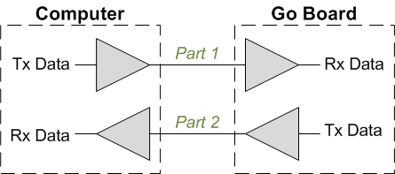
Let’s look at how the data is transmitted from the Computer to the Go Board:
The UART receiver will use a state machine to keep track of the data being received. The receiver first looks for the falling edge of the start bit. This indicates that a byte is being transmitted. It then waits for half of a bit period to align to the center of the UART data. The reason to use the center of the bits is that this is when you’re least likely to see transitions, and most likely to get a good sample of the UART data.
Once the receiver is aligned to the center, it samples the data on the line and stores each bit into a byte register. It increments an index to keep track of which bit is being received. Once all 8 data bits are received, it receives a stop bit, then returns to the IDLE state to wait for the next data byte.
I recommend that you give this project a try on your own. It’s a fun one!
Note that this UART Receiver is designed to be portable. Feel free to use it in any design you wish! Please give credit to www.nandland.com if you choose to use it! Both the VHDL and Verilog behave exactly the same way. Both the UART code and its associated testbench can be found at the links below:
UART Receiver and Testbench in VHDL
UART Receiver and Testbench in Verilog
Take some time really getting comfortable with the simulation environment. Again, knowing how to simulate your design is extremely helpful. It will save you so much time in the long run. Rather than debugging your code on hardware where you can’t see what’s going on, you’ll be debugging it in simulation where you can see all of your signals toggling. Once you’re confident that the low-level UART is correct, you can wrap up the design in another module.
The UART Receiver sends its received data to the o_RX_Data output. This data needs to be sent to the Binary to 7-Segment module that we created previously. We should wire the lower 4-bits into the lower segment and the upper 4-bits into the upper segment. Let’s take a look at how the top of this project looks.
VHDL Code – UART_RX_To_7_Seg_Top.vhd:
library ieee;
use ieee.std_logic_1164.all;

entity UART_RX_To_7_Seg_Top is
  port (
    -- Main Clock (25 MHz)
    i_Clk         : in std_logic;

    -- UART RX Data
    i_UART_RX : in std_logic;

    -- Segment1 is upper digit, Segment2 is lower digit
    o_Segment1_A  : out std_logic;
    o_Segment1_B  : out std_logic;
    o_Segment1_C  : out std_logic;
    o_Segment1_D  : out std_logic;
    o_Segment1_E  : out std_logic;
    o_Segment1_F  : out std_logic;
    o_Segment1_G  : out std_logic;

    o_Segment2_A  : out std_logic;
    o_Segment2_B  : out std_logic;
    o_Segment2_C  : out std_logic;
    o_Segment2_D  : out std_logic;
    o_Segment2_E  : out std_logic;
    o_Segment2_F  : out std_logic;
    o_Segment2_G  : out std_logic
    );
end entity UART_RX_To_7_Seg_Top;

architecture RTL of UART_RX_To_7_Seg_Top is

  signal w_RX_DV   : std_logic;
  signal w_RX_Byte : std_logic_vector(7 downto 0);

  signal w_Segment1_A, w_Segment2_A : std_logic;
  signal w_Segment1_B, w_Segment2_B : std_logic;
  signal w_Segment1_C, w_Segment2_C : std_logic;
  signal w_Segment1_D, w_Segment2_D : std_logic;
  signal w_Segment1_E, w_Segment2_E : std_logic;
  signal w_Segment1_F, w_Segment2_F : std_logic;
  signal w_Segment1_G, w_Segment2_G : std_logic;

begin

  UART_RX_Inst : entity work.UART_RX
    generic map (
      g_CLKS_PER_BIT => 217)            -- 25,000,000 / 115,200
    port map (
      i_Clk       => i_Clk,
      i_RX_Serial => i_UART_RX,
      o_RX_DV     => w_RX_DV,
      o_RX_Byte   => w_RX_Byte);

  -- Binary to 7-Segment Converter for Upper Digit
  SevenSeg1_Inst : entity work.Binary_To_7Segment
    port map (
      i_Clk        => i_Clk,
      i_Binary_Num => w_RX_Byte(7 downto 4),
      o_Segment_A  => w_Segment1_A,
      o_Segment_B  => w_Segment1_B,
      o_Segment_C  => w_Segment1_C,
      o_Segment_D  => w_Segment1_D,
      o_Segment_E  => w_Segment1_E,
      o_Segment_F  => w_Segment1_F,
      o_Segment_G  => w_Segment1_G
      );

  o_Segment1_A <= not w_Segment1_A;
  o_Segment1_B <= not w_Segment1_B;
  o_Segment1_C <= not w_Segment1_C;
  o_Segment1_D <= not w_Segment1_D;
  o_Segment1_E <= not w_Segment1_E;
  o_Segment1_F <= not w_Segment1_F;
  o_Segment1_G <= not w_Segment1_G;

  -- Binary to 7-Segment Converter for Lower Digit
  SevenSeg2_Inst : entity work.Binary_To_7Segment
    port map (
      i_Clk        => i_Clk,
      i_Binary_Num => w_RX_Byte(3 downto 0),
      o_Segment_A  => w_Segment2_A,
      o_Segment_B  => w_Segment2_B,
      o_Segment_C  => w_Segment2_C,
      o_Segment_D  => w_Segment2_D,
      o_Segment_E  => w_Segment2_E,
      o_Segment_F  => w_Segment2_F,
      o_Segment_G  => w_Segment2_G
      );

  o_Segment2_A <= not w_Segment2_A;
  o_Segment2_B <= not w_Segment2_B;
  o_Segment2_C <= not w_Segment2_C;
  o_Segment2_D <= not w_Segment2_D;
  o_Segment2_E <= not w_Segment2_E;
  o_Segment2_F <= not w_Segment2_F;
  o_Segment2_G <= not w_Segment2_G;

end architecture RTL;
Verilog Code – UART_RX_To_7_Seg_Top.v:
module UART_RX_To_7_Seg_Top
  (input i_Clk,     // Main Clock
   input i_UART_RX, // UART RX Data
   // Segment1 is upper digit, Segment2 is lower digit
   output o_Segment1_A,
   output o_Segment1_B,
   output o_Segment1_C,
   output o_Segment1_D,
   output o_Segment1_E,
   output o_Segment1_F,
   output o_Segment1_G,
   //
   output o_Segment2_A,
   output o_Segment2_B,
   output o_Segment2_C,
   output o_Segment2_D,
   output o_Segment2_E,
   output o_Segment2_F,
   output o_Segment2_G);

  wire w_RX_DV;
  wire [7:0] w_RX_Byte;

  wire w_Segment1_A, w_Segment2_A;
  wire w_Segment1_B, w_Segment2_B;
  wire w_Segment1_C, w_Segment2_C;
  wire w_Segment1_D, w_Segment2_D;
  wire w_Segment1_E, w_Segment2_E;
  wire w_Segment1_F, w_Segment2_F;
  wire w_Segment1_G, w_Segment2_G;

  // 25,000,000 / 115,200 = 217
  UART_RX #(.CLKS_PER_BIT(217)) UART_RX_Inst
  (.i_Clock(i_Clk),
   .i_RX_Serial(i_UART_RX),
   .o_RX_DV(w_RX_DV),
   .o_RX_Byte(w_RX_Byte));


  // Binary to 7-Segment Converter for Upper Digit
  Binary_To_7Segment SevenSeg1_Inst
  (.i_Clk(i_Clk),
   .i_Binary_Num(w_RX_Byte[7:4]),
   .o_Segment_A(w_Segment1_A),
   .o_Segment_B(w_Segment1_B),
   .o_Segment_C(w_Segment1_C),
   .o_Segment_D(w_Segment1_D),
   .o_Segment_E(w_Segment1_E),
   .o_Segment_F(w_Segment1_F),
   .o_Segment_G(w_Segment1_G));

  assign o_Segment1_A = ~w_Segment1_A;
  assign o_Segment1_B = ~w_Segment1_B;
  assign o_Segment1_C = ~w_Segment1_C;
  assign o_Segment1_D = ~w_Segment1_D;
  assign o_Segment1_E = ~w_Segment1_E;
  assign o_Segment1_F = ~w_Segment1_F;
  assign o_Segment1_G = ~w_Segment1_G;


  // Binary to 7-Segment Converter for Lower Digit
  Binary_To_7Segment SevenSeg2_Inst
  (.i_Clk(i_Clk),
   .i_Binary_Num(w_RX_Byte[3:0]),
   .o_Segment_A(w_Segment2_A),
   .o_Segment_B(w_Segment2_B),
   .o_Segment_C(w_Segment2_C),
   .o_Segment_D(w_Segment2_D),
   .o_Segment_E(w_Segment2_E),
   .o_Segment_F(w_Segment2_F),
   .o_Segment_G(w_Segment2_G));

  assign o_Segment2_A = ~w_Segment2_A;
  assign o_Segment2_B = ~w_Segment2_B;
  assign o_Segment2_C = ~w_Segment2_C;
  assign o_Segment2_D = ~w_Segment2_D;
  assign o_Segment2_E = ~w_Segment2_E;
  assign o_Segment2_F = ~w_Segment2_F;
  assign o_Segment2_G = ~w_Segment2_G;

endmodule
Now after building the code in iCEcube2, we should take a quick look at the synthesis results. This design uses 36 Registers (2%) and 80 LUTs (6%). This is less resources than the previous LED blink project, because the previous one had a few large counters in it. This one seems more complicated, but complicated code does not always imply more resource utilization. Let’s take a look at the programmed Go Board in action.
Okay, what’s going on here? The UART is clearly receiving something. The 7-Segment display appears to be working too, but we are seeing some strange numbers and hex characters appear on the display. This is actually the hex-encoded value of the ASCII buttons being pressed on the keyboard. ASCII is a look-up table for each key on the keyboard that represents each button as a hex digit from 00-FF. So we can see that the UART is working as expected!
Continue to Part 2: The UART Transmitter (the T part of UART)


the eda playground links point at projevts that require a commercial license. Took me a while to work out how to switch to the free stuff
In the module UART_RX design code, you have:
reg [7:0] r_Clock_Count;
reg [2:0] r_Bit_Index
reg [7:0] r_RX_Byte
reg [2:0] r_SM_Main
Does it matter if you define these as reg [7:0] vs reg [0:7]? Correspondingly, does it matter if you define reg [2:0] vs. reg [0:2]? I’m getting a little confused.
What does putting both w_Segment1_A and w_Segment2_A on the same line do as in your code:
wire w_Segment1_A, w_Segment2_A;
?
I was having a lot of problems getting my UART programs to work until I started disconnecting and reconnecting my Go Board after programming. Thank you for putting together these tutorials. With the Go Board and book I’m well on my way to fulfilling my FPGA dreams!
I’ve run into a problem that I don’t know how to fix. The Diamond Programmer has stopped working. Until tonight everything was working flawlessly, but now when I try to download a file I get the error : ERROR – Function:CHECK_ID Data Expected: h10 Actual: hFF. I’ve rebooted the system with no change in behavior. Do you have any ideas?
I’ve run into a problem that I don’t know how to fix. The Diamond Programmer has stopped working. Until tonight everything was working flawlessly, but now when I try to download a file I get the error : ERROR – Function:CHECK_ID Data Expected: h10 Actual: hFF. I’ve rebooted the system with no change in behavior. Do you have any ideas?
Try changing the Port from FTUSB-0 to FTUSB-1, or vice versa
I found the source of my problems – there was an errant penny underneath the board, now the circuit is a bit fried.
Haha oh no! that’s a new one! shoot me an email using the Contact page if you need to replace the Go Board.