Go Board – Simulating your FPGA
Let’s blink some LEDs and learn about Testbenches
Up until this point, we have been writing our code and then immediately building our FPGA on the Go Board. The problem with this type of design philosophy is that debugging your code while it is running on hardware is very hard to do. It’s much easier to find bugs before you program your code to your FPGA. This is done via Simulation. Here’s a normal build process:
- Write your HDL code (VHDL or Verilog)
- Simulate your HDL code
- Build your FPGA and test on Hardware
Those steps are normally done in order. Just because you finish writing your HDL code doesn’t mean it’s bug free. So you want to find and fix your bugs. The easiest place to find and fix bugs is in simulation. A simulation will try to exercise as much of your code as possible – including corner cases – to make sure that your code behaves appropriately.
I also created a YouTube video for this project, should you prefer to follow along with that.
Once you are reasonably sure the code behaves the way you would expect, you can program and test it on hardware. If you’ve written and simulated the code well, you won’t have any issues when you program your FPGA. No bugs on hardware should be the ultimate goal of a good FPGA designer. And the best way to ensure this happens is by simulating the hell out of your designs.
There are many different simulation programs available to Digital Designers. Traditionally, Modelsim is a popular program. When I initially designed the Go Board, I intended to use Modelsim to teach you how to write simulations. However, I figured dealing with licensing and downloading yet another program would be a pain. Instead, there’s a very neat web-based Simulator that Doulos puts out called EDA Playground.
First, let’s discuss how simulation works. Simulation describes placing your design or Unit Under Test (UUT) into a Testbench (TB), which stimulates its inputs and monitors its outputs. Your testbench exercises your design in the same way that it will be exercised on hardware. For example if your design takes a clock input, then your testbench will need to generate a simulated clock and provide it to your UUT.
Testbenches are critical pieces of writing FPGA code. Being able to write really good testbenches makes your life a lot easier, because it means that you won’t have to find bugs on the actual hardware. Again, finding bugs on hardware is hard! The very best testbenches are self-checking which means that they can be run and report a PASS or FAIL status, without the user having to do anything else. These take a long time to get set up, but they’re worth it in the long run.
The other thing about testbench code is that it does not have to be synthesizable. Up until this point, we’ve only ever dealt with parts of VHDL and Verilog that are able to be synthesized by iCEcube2. Now we are going to introduce more parts of both languages that are never meant to be synthesized but ARE useful in simulation. Keep this concept in mind of code for synthesis vs. code for simulation, it’s very important not to mix simulation code in to your synthesizable code!
For now, we’re going to be doing non-self-checking testbenches and looking at waveforms to make sure that our design is behaving as expected. The design that we’re going to do is pretty simple, the purpose of this tutorial is to learn about simulation.
Project Description
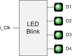
Make the LEDs on the Go Board blink at different rates: 1 Hz, 2 Hz, 5 Hz, and 10 Hz
Now that we are using all four LEDs on the Go Board, we need to keep the state of each LED individually. Additionally, since each LED blinks at a different rate, then we will need to keep counters to keep track of time for each LED. Let’s get started with looking at the Simulation environments for both VHDL and Verilog.
VHDL Simulation
For the VHDL solution, go to this playground. You will be greeted with two files in front of you. Let’s first look at the file on the right, which is the LED Blink code. The purpose of this code is to create four processes. Each process controls one of the LEDs. They each count up until they reach their specified value, then they toggle the state of the LED to make it blink.
Now look at the file on the left of the screen. This is your Testbench file. The purpose of this code is to stimulate your UUT to test it. You will be observing how the UUT responds to stimulus and verifying that it is behaving as you expect it to. This code will not actually be used to build the FPGA, it’s not going to be synthesized.
In the code for the design this is the first time that we have introduced generics in VHDL. A generic is used to make your code more portable and reusable. If your clock frequency changes, you do not need to change values inside your VHDL code. Instead, you just need to modify your generics, which can be set by the instantiating module. This is useful in testbenches too. Look at the file on the left half of the screen in EDA Playground.
The testbench sets the generics to values that are much smaller than the values that we will use for synthesis. The purpose of this is to speed up the simulation time. If the simulation needed to count up to 200000, it would take a long time to run. For the interest of time, let’s just set those generics to be smaller values. This is done in the testbench file on the left.
The other thing that you’ll see in the testbench is this line:
r_Clock <= not r_Clock after c_CLK_PERIOD/2;
This is the first time we have seen code that is NOT SYNTHESIZABLE. The line above is purely for simulation only. The keyword after is introduced here, and it relies on time. Remember that the FPGA has no knowledge of time. It doesn’t know how long 1 nanoseconds is, it only can count clock cycles. This is how you are able to keep track of time: counting clock cycles. This is precisely how the design works to toggle the LEDs.
Running the Simulation
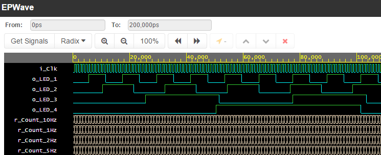
To run the simulation, click the Run button at the top. When the simulation is complete, the EPWave should open. This allows you to look at the waveforms to verify that everything is behaving as expected. You will need to get signals to look at. Click Get Signals, Click LED_Blink_Inst, then Click Append All. You should see the waveforms in the UUT.
As you can see in the waveforms, the counters inside the code are counting correctly and the LEDs are toggling. Congratulations, the testbench shows that your design is probably going to work on hardware. Now we need to instantiate the file at the top-level of our FPGA design. This is required because we need to set the generics to their correct value. Let’s look at that code.
VHDL Code – LED_Blink_Top.vhd:
library ieee;
use ieee.std_logic_1164.all;

entity LED_Blink_Top is
  port (
    i_Clk   : in  std_logic;
    o_LED_1 : out std_logic;
    o_LED_2 : out std_logic;
    o_LED_3 : out std_logic;
    o_LED_4 : out std_logic
    );
end LED_Blink_Top;

architecture RTL of LED_Blink_Top is

begin

  -- Input clock is 25 MHz
  -- Generics represent count values to which internals count
  -- before toggling their LEDs
  LED_Blink_Inst : entity work.LED_Blink
    generic map (
      g_COUNT_10HZ => 1250000,
      g_COUNT_5HZ  => 2500000,
      g_COUNT_2HZ  => 6250000,
      g_COUNT_1HZ  => 12500000)
    port map (
      i_Clk   => i_Clk,
      o_LED_1 => open,    -- this is perfectly OK to do
      o_LED_2 => o_LED_2,
      o_LED_3 => o_LED_3,
      o_LED_4 => o_LED_4
      );

end RTL;
Verilog Simulation
For the Verilog solution, go to this playground. You will be greeted with two files in front of you. Let’s first look at the file on the right, which is the LED Blink code. The purpose of this code is to create four always blocks. Each always block controls one of the LEDs. They each count up until they reach their specified value, then they toggle the state of the LED to make it blink.
Now look at the file on the left of the screen. This is your Testbench file. The purpose of this code is to stimulate your UUT to test it. You will be observing how the UUT responds to stimulus and verifying that it is behaving as you expect it to. This code will not actually be used to build the FPGA, it’s not going to be synthesized.
In the code for the design this is the first time that we have introduced parameters in Verilog. A parameter is used to make your code more portable and reusable. If your clock frequency changes, you do not need to change values inside your Verilog code. Instead, you just need to modify your parameters, which can be set by the instantiating module. This is useful in testbenches too. Look at the file on the left half of the screen in EDA Playground.
The testbench sets the parameters to values that are much smaller than the values that we will use for synthesis. The purpose of this is to speed up the simulation time. If the simulation needed to count up to 200000, it would take a long time to run. For the interest of time, let’s just set those parameters to be smaller values. This is done in the testbench file on the left.
The other thing that you’ll see in the testbench is this line:
always #1 r_Clock <= ~r_Clock;
This is the first time we have seen code that is NOT SYNTHESIZABLE. The line above is purely for simulation only. The pound sign (#) is introduced here, and it relies on time. It means that the clock will wait for 1 simulation time before it changes again. Remember that the FPGA has no knowledge of time. It doesn’t know how long 1 nanoseconds is, it only can count clock cycles. This is how you are able to keep track of time: counting clock cycles. This is precisely how the design works to toggle the LEDs.
Running the Simulation
To run the simulation, click the Run button at the top. When the simulation is complete, the EPWave should open. Note that the $dumpfile(“dump.vcd”) code is required to dump the signals to create the EPWave. EPWave allows you to look at the waveforms to verify that everything is behaving as expected. You will need to get signals to look at. Click Get Signals, Click LED_Blink_Inst, then Click Append All. You should see the waveforms in the UUT.
As you can see in the waveforms, the counters inside the code are counting correctly and the LEDs are toggling. Congratulations, the testbench shows that your design is probably going to work on hardware. Now we need to instantiate the file at the top-level of our FPGA design. This is required because we need to set the generics to their correct value. Let’s look at that code.
Verilog Code – LED_Blink_Top.v:
module LED_Blink_Top
 (input  i_Clk,
  output o_LED_1,
  output o_LED_2,
  output o_LED_3,
  output o_LED_4);

  // Input clock is 25 MHz
  // Generics represent count values to which internals count
  // before toggling their LEDs
  LED_Blink #(.g_COUNT_10HZ(1250000),
              .g_COUNT_5HZ(2500000),
              .g_COUNT_2HZ(6250000),
              .g_COUNT_1HZ(12500000)) LED_Blink_Inst
    (.i_Clk(i_Clk),
     .o_LED_1(),    // this is perfectly OK to do
     .o_LED_2(o_LED_2),
     .o_LED_3(o_LED_3),
     .o_LED_4(o_LED_4));

endmodule
Building the Project
The build process for this project is exactly the same as the other projects that we done in the past. Take a look at your Synthesis results and the results of Place and Route.
Synthesis Results (Condensed):
Register bits not including I/Os:   99 (7%)
Total  LUTs: 123 (9%)
Place and Route Timing Results:
Number of clocks: 1
Clock: i_Clk  | Frequency: 178.01 MHz  | Target: 25.00 MHz  |
When you build the code and program the Go Board you’ll see that the LEDs are blinking as expected! Notice that LED 1 is not blinking, do you know why this is? Congratulations on your first project that uses simulation! From this point forward, the rest of the Go Board projects are getting more complicated. All will require simulation as part of the design. Now that you have a good introduction on how simulating a design works, the next project will use simulations to test out a much more complicated design: A UART.
Next: Design and Simulate a UART – Communication From Your Computer to The Go Board


Is LED_Blink_Top.v supposed to be equivalent to the tutorial_led_blink.v code that’s shown on the
nandland.com/your-first-vhdl-progam-an-led-blinker
webpage?
If so, they look totally different with the tutorial_led_blink.v code being significantly longer. Does the LED_Blink_Top.v code serve a different purpose?