Signed vs. Unsigned in VHDL
All Digital Designers must understand how math works inside of an FPGA or ASIC. The first step to that is understanding how signed and unsigned signal types work. Signed and unsigned types exist in the numeric_std package, which is part of the ieee library. It should be noted that there is another package file that is used frequently to perform mathematical operations: std_logic_arith. However, std_logic_arith is not an official ieee supported package file and it is not recommended for use in digital designs.
A signal that is defined as type signed means that the tools interpret this signal to be either positive or negative. A signal that is defined as type unsigned means that the signal will be only positive. Internally, the FPGA will use Two’s Complement representation. For example, a 3-bit signal can be interpreted according to the table below:
| Bits | Unsigned Value | Signed Value |
|---|---|---|
| 011 | 3 | 3 |
| 010 | 2 | 2 |
| 001 | 1 | 1 |
| 000 | 0 | 0 |
| 111 | 7 | -1 |
| 110 | 6 | -2 |
| 101 | 5 | -3 |
| 100 | 4 | -4 |
Are you confused yet? You should be, this is not intuitive! Let’s look at an example which will hopefully clear things up. The file below tests out how signed unsigned works. What needs to be understood is that whether or not the signals are defined as signed or unsigned does not affect how the actual binary math is performed.
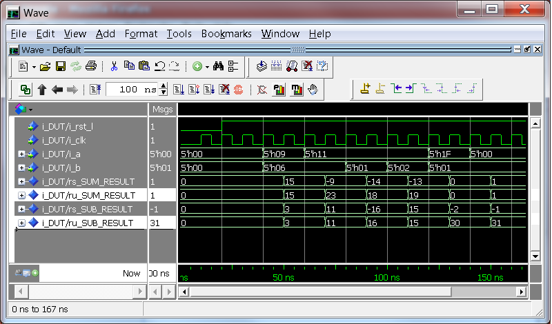
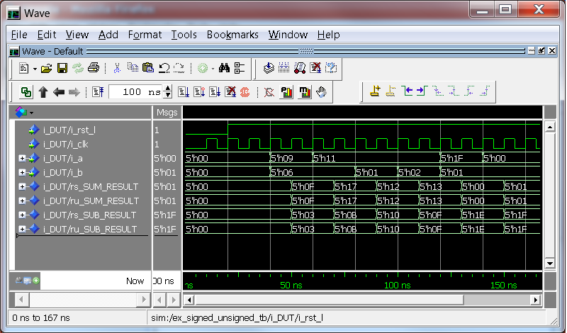
For example: For two signed vectors 10001 + 00010 the answer is still 10011, BUT it’s the interpretation of the result that is different.
For the unsigned case, the answer (10011) represents 19.
For the signed case, the answer (10011) represents -13.
library ieee;
use ieee.std_logic_1164.all;
use ieee.numeric_std.all;


entity signed_unsigned is
  port (
    i_rst_l : in std_logic;
    i_clk   : in std_logic;
    i_a     : in std_logic_vector(4 downto 0);
    i_b     : in std_logic_vector(4 downto 0)
    );
end signed_unsigned;

architecture behave of signed_unsigned is
  signal rs_SUM_RESULT : signed(4 downto 0)   := (others => '0');
  signal ru_SUM_RESULT : unsigned(4 downto 0) := (others => '0');
  signal rs_SUB_RESULT : signed(4 downto 0)   := (others => '0');
  signal ru_SUB_RESULT : unsigned(4 downto 0) := (others => '0');

begin

  -- Purpose: Add two numbers.  Does both the signed and unsigned
  -- addition for demonstration.  This process is synthesizable.
  p_SUM : process (i_clk, i_rst_l)
  begin
    if i_rst_l = '0' then             -- asynchronous reset (active low)
      rs_SUM_RESULT <= (others => '0');
      ru_SUM_RESULT <= (others => '0');
    elsif rising_edge(i_clk) then

      ru_SUM_RESULT <= unsigned(i_a) + unsigned(i_b);
      rs_SUM_RESULT <= signed(i_a) + signed(i_b);

    end if;

  end process p_SUM;


  -- Purpose: Subtract two numbers.  Does both the signed and unsigned
  -- subtraction for demonstration.  This process is synthesizable.
  p_SUB : process (i_clk, i_rst_l)
  begin
    if i_rst_l = '0' then             -- asynchronous reset (active low)
      rs_SUB_RESULT <= (others => '0');
      ru_SUB_RESULT <= (others => '0');
    elsif rising_edge(i_clk) then

      ru_SUB_RESULT <= unsigned(i_a) - unsigned(i_b);
      rs_SUB_RESULT <= signed(i_a) - signed(i_b);

    end if;

  end process p_SUB;

end behave;
Testbench:
library ieee;
use ieee.std_logic_1164.all;

entity example_signed_unsigned_tb is
end example_signed_unsigned_tb;

architecture behave of example_signed_unsigned_tb is

  --Registers
  signal r_CLK   : std_logic                    := '0';
  signal r_RST_L : std_logic                    := '0';
  signal r_A     : natural                      := 0;
  signal r_B     : natural                      := 0;
  signal r_A_SLV : std_logic_vector(4 downto 0) := (others => '0');
  signal r_B_SLV : std_logic_vector(4 downto 0) := (others => '0');

  constant c_CLK_PERIOD : time := 10 ns;

  component example_signed_unsigned is
    port (
      i_rst_l        : in  std_logic;
      i_clk          : in  std_logic;
      i_a            : in  std_logic_vector(4 downto 0);
      i_b            : in  std_logic_vector(4 downto 0)
      );
  end component example_signed_unsigned;

begin

  i_DUT: example_signed_unsigned
    port map (
     i_rst_l          => r_RST_L,
     i_clk            => r_CLK,
     i_a              => r_A_SLV,
     i_b              => r_B_SLV
     );


  clk_gen : process is
  begin
    r_CLK <= '0' after c_CLK_PERIOD/2, '1' after c_CLK_PERIOD;
    wait for c_CLK_PERIOD;
  end process clk_gen;


  process
  begin

    r_RST_L <= '0';
    wait for 20 ns;
    r_RST_L <= '1';
    wait for 20 ns;

    r_A_SLV <= "01001";
    r_B_SLV <= "00110";
    wait for 20 ns;

    r_A_SLV <= "10001";
    r_B_SLV <= "00110";
    wait for 20 ns;

    r_A_SLV <= "10001";
    r_B_SLV <= "00001";
    wait for 20 ns;

    r_A_SLV <= "10001";
    r_B_SLV <= "00010";
    wait for 20 ns;

    r_A_SLV <= "11111";
    r_B_SLV <= "00001";
    wait for 20 ns;

    r_A_SLV <= "00000";
    r_B_SLV <= "00001";
    wait for 20 ns;
    wait;

  end process;

end behave;

Simulation Output of Signed vs. Unsigned in Decimal

Simulation Output of Signed vs. Unsigned in Hex
Compare the two modelsim screenshots above. In the first you can see that the results of the mathematical functions are exactly the same when represented in hex. It’s the interpretation of the results that is different. This can be seen by looking at the bottom screenshot. When Modelsim displays the results in decimal it interprets some of them as negative numbers. When using signed and unsigned types you must be very careful! Hopefully you understand this topic a little better. I feel like this is an area that many digital designers struggle with, so if there is something that you do not fully understand please send me an email via the Contact Link on the Sidebar and I will try to make it clearer.
| Most Popular Nandland Pages | |
|---|---|
| Avoid Latches in your FPGA Learn what is a latch and how they are created. Usually latches are created by accident. Learn the simple trick to avoid them. |
Example Code for UART See example VHDL and Verilog code for a UART. See the basics of UART design and use this fully functional design to implement your own UART. Good example of a state machine. |
| Convert Binary to BCD Binary Coded Decimal (BCD) is used to display digits on a 7-Segment display, but internal signals in an FPGA use binary. This module converts binary to BCD using a double-dabbler. |
What is a FIFO? Learn the basics of a FIFO. There are two simple rules governing FIFOs: Never write to a full FIFO and Never Read from an Empty FIFO… |


Leave A Comment