What is a Multiplexer (Mux) in an FPGA?
Create a Mux in Verilog and VHDL
A multiplexer (or Mux) is another word for a selector. It acts much like a railroad switch. This picture shows two possible source tracks that can be connected to a single destination track. The railroad switch controls via some external control which train gets to connect to the destination track. This exact same concept is used with a 2-1 Mux. Two inputs can connect to a single output.
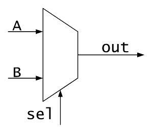
Multiplexers are used all the time in FPGAs in various sizes and configurations. This image shows what a 2 to 1 mux looks like symbolically. The inputs to the mux are A, B, sel, the output is out. A and B are the Data inputs that get selected to the output. sel is your control signal. Muxes can come in all possible combinations, depending on your particular use case. Typically, some number of inputs are selected to a single output. However the reverse could be true and it would still be a mux. A single input could be selected to any number of outputs. The examples below demonstrate a 2-1 and a 4-1 multiplexer in both VHDL and Verilog.
The code below uses all combinational code, meaning no clocks are needed in the design. Ensure that when you write your combinational code that your assignments are complete. An incomplete assignment can generate a latch, which you almost surely do not want to do. It is important to note that a mux is not actually a dedicated piece of logic on your FPGA. A mux is constructed out of Look-Up Table (LUT) elements inside your chip.
It should be stated that when you’re actually designing switches (muxes) in your FPGA design, you will almost never be creating a dedicated module for them. A mux is too simple to require its own instantiation. You’re better off just putting the mux code into whatever file needs to do the switching. In general, when trying to answer the question, “Should this be in its own module?” you should ask yourself how often is the code going to be reused and if making it a dedicated module will be easier than writing the code each time you need it. For a mux, it’s actually more code to make it portable, rather than just designing a mux where and when you need it.
Verilog Implementation of Multiplexers
Simple 2 to 1 Mux in Verilog:
module Mux_2_To_1 (input  i_Select,
                   input  i_Data1,
                   input  i_Data2,
                   output o_Data);

  assign o_Data = i_Select ? i_Data1 : i_Data2;

endmodule // Mux_2_To_1
2 to 1 Mux in Verilog (array of bits):
module Mux_2_To_1_Width #(parameter g_WIDTH = 8)
  (input  i_Select,
   input  [g_WIDTH-1:0] i_Data1,
   input  [g_WIDTH-1:0] i_Data2,
   output [g_WIDTH-1:0] o_Data);

  assign o_Data = i_Select ? i_Data1 : i_Data2;

endmodule // Mux_2_To_1_Width
4 to 1 Mux in Verilog:
module Mux_4_To_1 (input [1:0] i_Select,
                   input  i_Data1,
                   input  i_Data2,
                   input  i_Data3,
                   input  i_Data4,
                   output o_Data);

  reg r_Data;

assign o_Data = i_Select[1] ? (i_Select[0] ? i_Data4 : i_Data3) :
                              (i_Select[0] ? i_Data2 : i_Data1);


// Alternatively:
always @(*)
begin
  case (i_Select)
    2'b00 : r_Data <= i_Data1;
    2'b01 : r_Data <= i_Data2;
    2'b10 : r_Data <= i_Data3;
    2'b11 : r_Data <= i_Data4;
  endcase // case (i_Select)
end

assign o_Data = r_Data;

endmodule // Mux_4_To_1
VHDL Implementation of Multiplexers
Simple 2 to 1 Mux in VHDL:
library ieee;
use ieee.std_logic_1164.all;

entity Mux_2_To_1 is
  port (
    i_Select : in  std_logic;
    i_Data1  : in  std_logic;
    i_Data2  : in  std_logic;
    o_Data   : out std_logic
    );
end entity Mux_2_To_1;

architecture RTL of Mux_2_To_1 is
begin
  o_Data <= i_Data1 when i_Select = '0' else i_Data2;
end architecture RTL;
2 to 1 Mux in VHDL (using std_logic_vector):
library ieee;
use ieee.std_logic_1164.all;

entity Mux_2_To_1_Width is
  generic (
    g_WIDTH : integer := 8);   -- Override when instantiated
  port (
    i_Select : in  std_logic;
    i_Data1  : in  std_logic_vector(g_WIDTH-1 downto 0);
    i_Data2  : in  std_logic_vector(g_WIDTH-1 downto 0);
    o_Data   : out std_logic_vector(g_WIDTH-1 downto 0)
    );
end entity Mux_2_To_1_Width;

architecture RTL of Mux_2_To_1_Width is
begin
  o_Data <= i_Data1 when i_Select = '0' else i_Data2;
end architecture RTL;
4 to 1 Mux in VHDL:
library ieee;
use ieee.std_logic_1164.all;

entity Mux_4_To_1 is
  port (
    i_Select : in  std_logic_vector(1 downto 0);
    i_Data1  : in  std_logic;
    i_Data2  : in  std_logic;
    i_Data3  : in  std_logic;
    i_Data4  : in  std_logic;
    o_Data   : out std_logic
    );
end entity Mux_4_To_1;

architecture RTL of Mux_4_To_1 is
begin
  o_Data <= i_Data1 when i_Select = "00" else
            i_Data2 when i_Select = "01" else
            i_Data3 when i_Select = "10" else
            i_Data4;

  -- Alternatively:
  with i_Select select
    o_Data <= i_Data1 when "00", i_Data2 when "01", i_Data3 when "10", i_Data4 when others; -- Alternatively: p_Mux: process (i_Select, i_Data1, i_Data2, i_Data3, i_Data4) is begin case i_Select is when "00" =>
        o_Data <= i_Data1; when "01" =>
        o_Data <= i_Data2; when "10" =>
        o_Data <= i_Data3; when others =>
        o_Data <= i_Data4;
    end case;
  end process p_Mux;

end architecture RTL;


Leave A Comment