Tutorial – How Flip-Flops Work in FPGAs
In the previous article, we discussed the Look-Up Table (LUT) component. This is one of the two most important components inside of an FPGA, the other most important component is the Flip-Flop. There are a few different types of flip-flops (JK, T, D) but the one that is used most frequently is the D Flip-Flop.
Notice in the picture above there is a pin on the top of the device labeled S. This is known as the Set pin. On the bottom of the device there is a pin labeled R. This is known as the Reset pin. Additionally, on the right side of the device, there is a pin labeled Qbar. This pin will always contain the opposite value of the value on pin Q. Now that you know what those pins are, let’s ignore them! They are important, but they are not the focus of this article. The three most imporant pins on the Flip-Flop are:
    D    Data Input to Flip-Flop
    Q    Data Output of Flip-Flop (Registered)
    >    Clock Input to Flip-Flop
The first question you might be asking yourself is, what is a clock?
Digital clocks are what makes almost all digital circuits operate. One way to think about the clock in a system is to think of set of gears. In order for any gear in the system to turn, there must be some master gear that drives all the others. That is effectively the purpose of the clock in digital logic. It provides a steady stream of low-to-high-to-low again transitions of a voltage that lets your FPGA chug along. Plus the analogy is fun because the gears look a bit like the square wave of a digital clock.
The clock is what allows a Flip-Flop to be used as a data storage element. Any data storage elements are known as sequential logic or registered logic. Sequential logic operates on the transitions of a clock. 99.9% of the time this will be the rising edge (when the clock goes from 0 to 1). When a Flip-Flop sees a rising edge of the clock, it registers the data from the Input D to the Output Q. Flip-Flops are what make complex FPGAs possible! Let’s look at a waveform of a few events.
The above waveform shows three clock cycle events, represented by the red arrow on the rising edge of the clock. In between the first and second rising edge of the clock, the D input goes from low to high. The output Q sees that D has gone from low to high at the rising edge of the second clock cycle. The rising edge is when the Flip Flop looks at the input data. At this point, Q becomes the same value as input D. On the third rising edge, Q again checks the value of D and registers it (this is why flip-flops are often referred to as registers). Since it has not changed, Q stays high. Let’s look at another waveform.
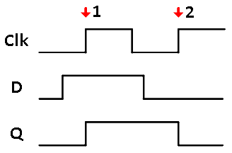
The above image shows a waveform of two inputs and one output for a D Flip-Flop. The D Flip-Flop is sensitive to the rising edge of the clock, so when the rising edge comes along, the input D is passed along to the output Q. This only occurs on the edges. On the first clock cycle, Q sees that D has become 1, so it toggles from 0 to 1. On the second clock edge, Q again checks the value of D and sees that it is low again, so it becomes low.
Now that you understand how they work, let’s discuss why they are so crucial to digital design. Again, I mentioned that flip-flops and LUTs are the two most important components inside of an FPGA. The concept of how flip-flops (registers) work is crucial to becoming a good digital designer. These little guys are everywhere! Flip-flops are the main component in an FPGA that is used to keep the state inside of the chip.
If everything was just made of LUTs, there would be no way to keep state in the FPGA. This means the FPGA would have no idea what happened previously. All changes on the inputs would immediately be evaluated and sent to the output with a very long chain of and gates, or gates, etc. But in order to do the vast majority of tasks an FPGA needs to know something about the past. This way it can keep track of counters, state machines, and the status of things. Flip-flops make this possible. If you still don’t quite grasp this concept yet, that’s OK. It’s an abstract way of thinking. The importance of flip-flops in your FPGA designs will become more apparent the more you work with a Hardware Description Language (HDL).
Now that you have learned the basics of digital design, let’s start learning an HDL!


Leave A Comment